


News
- Home
- Service
- Product Center
- Application
- About Us
- Videos
- News
- Contact Us

2025-08-29 14:53:58
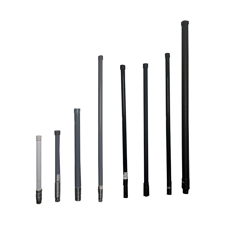
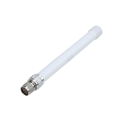
A global positioning system (GPS) antenna is a specialized radio frequency (RF) device designed to receive and amplify the low-power L-band microwave signals transmitted by a constellation of satellites orbiting the Earth. Its primary function is to act as the front-end of a GPS receiver system, capturing these faint signals—which typically arrive at the Earth's surface with a signal strength as low as -130 dBm—and amplifying them with minimal addition of intrinsic noise, a quality measured by its Noise Figure (NF), often below 2.0 dB. This pre-amplified signal is then passed via a coaxial cable to the GPS receiver module, which performs the complex calculations of trilateration to determine precise geographic coordinates, velocity, and time.
The operational effectiveness of a gps antenna is defined by several critical technical parameters. Firstly, its gain pattern is crucial; most are designed to be hemispherical (passive antennas) or have a pre-amplifier (active antennas) to provide a gain between 25 dB to 30 dB, ensuring a clear view of the sky and satellites low on the horizon. The polarization is almost exclusively Right-Hand Circular Polarization (RHCP), which is matched to the satellite transmissions to mitigate signal degradation caused by atmospheric conditions and multipath effects—where signals bounce off obstacles like buildings. Key performance metrics include the axial ratio, which should be as low as 3 dB to maintain polarization purity, and the voltage standing wave ratio (VSWR), ideally below 2.0:1, indicating efficient power transfer from the antenna to the coaxial cable. For active antennas, the supply voltage and current draw are also vital, typically operating on 3.3V or 5V DC and consuming between 5mA to 30mA of current, supplied through the coaxial cable via a bias-tee circuit within the receiver.
Frequency Band: Operates on the L1 band at 1575.42 MHz (±1.023 MHz) for standard positioning service. Many modern antennas are also multi-band, supporting L2 (1227.60 MHz) and L5 (1176.45 MHz) for advanced applications requiring higher accuracy and interference resistance.
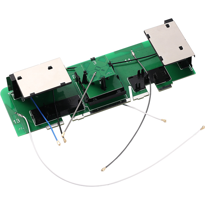
Gain: Typically features a peak gain of >5 dBiC for passive antennas. Active antennas incorporate a Low-Noise Amplifier (LNA) to provide a total gain of 25 dB to 30 dB, compensating for cable losses.
Noise Figure (NF): A critical specification for the internal LNA, representing the degradation of the signal-to-noise ratio (SNR). High-quality antennas maintain an NF below 1.5 dB to ensure sensitivity to the weakest signals.
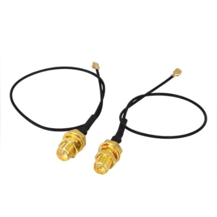
Impedance: Standard impedance is 50 Ohms, matched to most RF coaxial cables (e.g., RG-174, RG-58) to minimize signal reflections.
Axial Ratio: A measure of circular polarization purity. A ratio of <3 dB across the upper hemisphere is considered excellent for rejecting multipath signals and maintaining accuracy.
VSWR: Typically <2.0:1 across the entire operating band, indicating efficient RF power transfer and minimal signal reflection.
Phase Center Stability: For high-precision geodetic and survey-grade antennas, the phase center must be extremely stable (variations <2mm) to ensure centimeter-level accuracy, as any movement directly translates to positional error.
The utility of gps antennas spans countless industries due to the fundamental need for positioning, navigation, and timing (PNT).
Automotive and Telematics: Integrated into vehicle infotainment and Advanced Driver-Assistance Systems (ADAS) for real-time navigation, stolen vehicle recovery, and usage-based insurance. High-dynamic-range antennas are required to handle the varying signal conditions.
Aviation and Maritime: Critical for the navigation of aircraft (as part of the FAA's Wide Area Augmentation System - WAAS) and vessels. These applications demand highly reliable antennas with superior multipath rejection and often support for multiple satellite constellations (GPS, GLONASS, Galileo, BeiDou).
Precision Agriculture: Enables autonomous tractor guidance and variable-rate technology (VRT) for seeding, fertilizing, and harvesting. This requires Real-Time Kinematic (RTK) GPS systems with centimeter-level accuracy, driven by highly stable, survey-grade antennas.
Surveying and Geomatics: Professional land surveyors use tripod-mounted geodetic antennas with precisely known and stable phase centers to establish control points and create accurate maps.
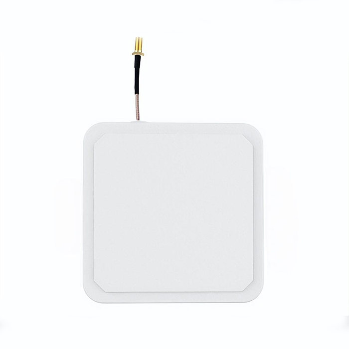
Consumer Electronics: Embedded in smartphones, smartwatches, fitness trackers, and digital cameras for location tagging (geotagging), fitness monitoring, and personal navigation. These designs prioritize miniaturization (e.g., ceramic Patch Antennas) and power efficiency.
Scientific and Timing Applications: Used in seismology to measure tectonic plate movements and as a source for precise time synchronization (Network Time Protocol - NTP servers) in telecommunications networks, financial trading systems, and data centers.
Unmanned Systems: Essential for the navigation and stable flight control of Unmanned Aerial Vehicles (UAVs or drones), both for recreational and commercial applications like aerial photography and infrastructure inspection.
Proper maintenance is essential to ensure the long-term reliability and accuracy of a GPS antenna system. The following procedures should be adhered to:
Physical Inspection and Cleaning: Periodically inspect the antenna housing, radome, and connector for any signs of physical damage, such as cracks, corrosion, or water ingress. Gently clean the radome (the protective plastic cover) with a soft cloth and a mild, non-abrasive detergent solution to remove dirt, salt spray, or bird droppings that can attenuate the RF signal. Avoid using harsh chemicals or abrasive materials that could scratch or damage the surface.
Connector Integrity: The coaxial connector (typically an SMA or TNC type) is a critical point of failure. Check that it is securely fastened to the receiver port to prevent moisture ingress and signal loss. Inspect for any signs of corrosion or oxidation on the metal contacts. If corrosion is present, clean it carefully with contact cleaner and a soft brush. Ensure the central pin is not bent or damaged.
Cable Inspection: Examine the entire length of the coaxial cable for cuts, abrasions, crushing, or rodent damage. A compromised cable can lead to significant signal attenuation, ingress of noise, and ultimately system failure. The cable should be routed away from sharp edges and potential sources of heat.
Mounting and Grounding: Verify that the antenna mount remains tight and secure. Vibration can loosen mounts over time, potentially misaligning the antenna and degrading performance. For permanent installations, ensure the grounding system is intact to protect the antenna and connected equipment from electrostatic discharge (ESD) and lightning-induced surges.
Performance Monitoring: Be aware of the system's typical performance metrics, such as time-to-first-fix (TTFF) and the number of satellites tracked. A sudden degradation in performance could indicate a failing antenna, amplifier, cable, or connector. Use diagnostic tools within the GPS receiver software to check signal strength levels.
Storage: If the antenna is to be stored for an extended period, keep it in a dry, cool environment inside a protective anti-static bag to prevent moisture accumulation and damage to the internal electronics.


Address: No.1 Sankeng Qinghutou Tangxia Dongguan Guangdong China TaiWan office: 558-2 ZhongHua,Zhubei,Xinzhu,Taiwan
Copyright © 2026 Dongguan RenFeng Electronic Technology Co.,Ltd All rights reserved.