


News
- Home
- Service
- Product Center
- Application
- About Us
- Videos
- News
- Contact Us

2025-09-20 14:52:16
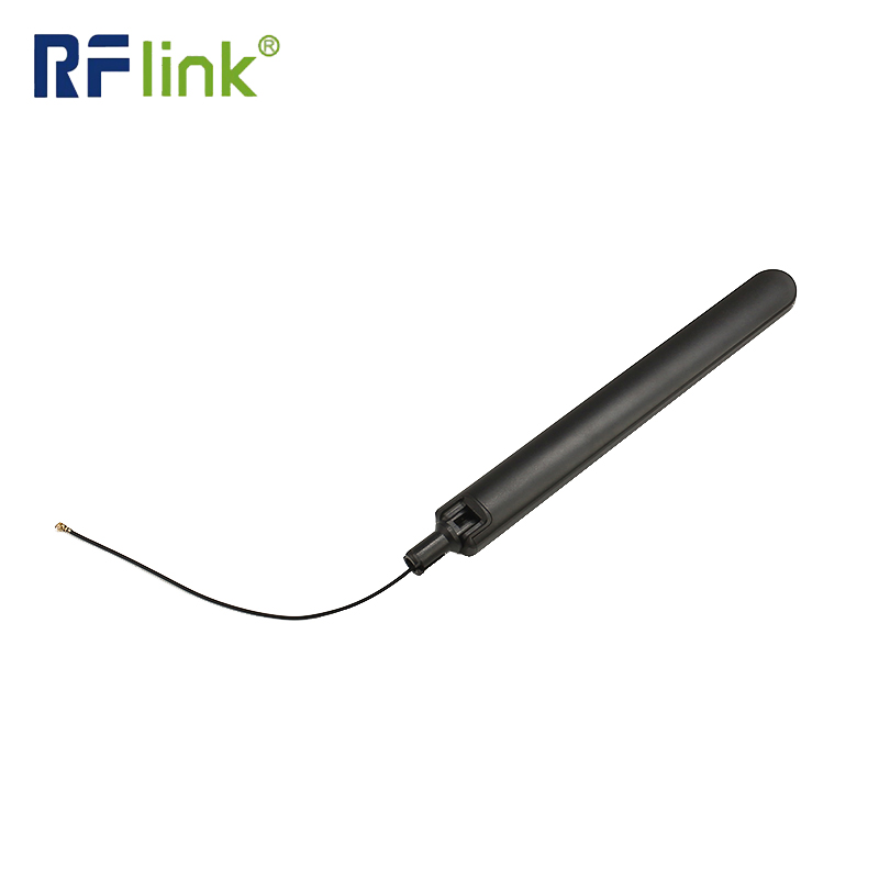
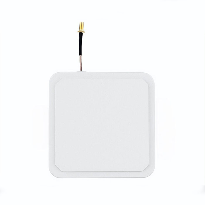
An RFID (Radio Frequency Identification) antenna is a critical transducer component within an RFID system, responsible for converting electrical signals from the interrogator (reader) into propagating electromagnetic waves and vice versa. It establishes the essential wireless communication link between the reader and the passive or active RFID tags. The antenna's design and performance directly govern the system's read range, reliability, and overall efficacy. Unlike a simple coil, modern RFID Antennas are sophisticated devices engineered for specific frequency bands, polarization, and radiation patterns to optimize energy transfer and data exchange in diverse environments.
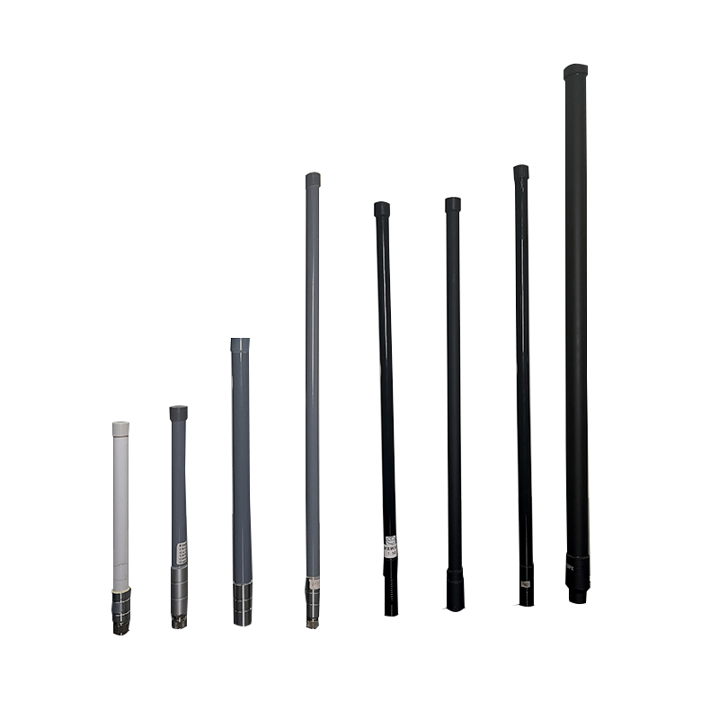
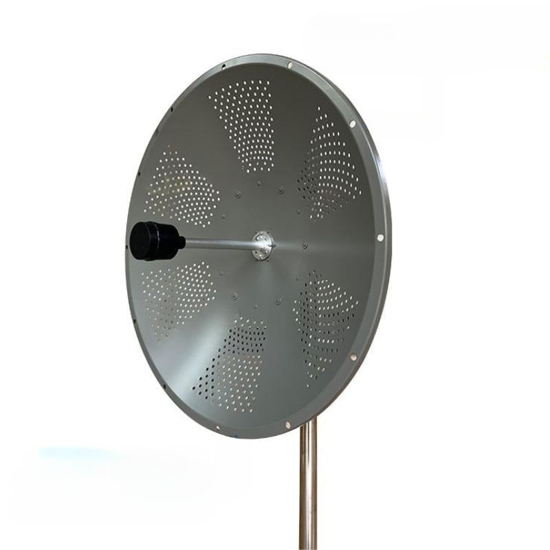
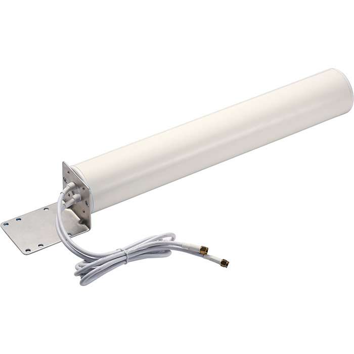
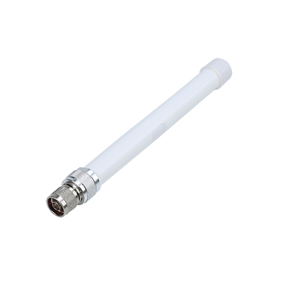
The performance of an RFID Antenna is quantified by several key electrical and physical parameters. Operating Frequency is fundamental; Low-Frequency (LF) antennas operate at 125-134 kHz, High-Frequency (HF) antennas at 13.56 MHz, and Ultra-High-Frequency (UHF) antennas at 860-960 MHz, with UHF antennas offering the longest read ranges, typically from 5 to 12 meters for passive tags, due to their shorter wavelengths and higher data transfer rates. The Gain, measured in dBi (decibels isotropic), indicates the directionality and power concentration of the radiated signal. Linear polarized UHF antennas typically feature gains between 6 dBi and 10 dBi, while circularly polarized antennas, which are less sensitive to tag orientation, have slightly lower gains, usually between 3 dBi and 8 dBi, to ensure robust coverage.
Beamwidth, the angular width of the antenna's radiation pattern, is inversely related to gain. A high-gain 9 dBi antenna might have a narrow beamwidth of 60°, focusing energy for long-range portal reading, whereas a 4 dBi antenna could have a wide 100° beamwidth for short-range, broad-area coverage. Polarization is another critical factor; linear antennas (vertical or horizontal) offer maximum range when the tag's antenna is aligned but suffer from polarization mismatch losses. Circularly polarized antennas radiate energy in a corkscrew pattern, mitigating orientation-based losses and providing more consistent reads for arbitrarily oriented tags, albeit with a reduction of approximately 3 dB in effective radiated power (ERP) compared to a perfectly aligned linear antenna.
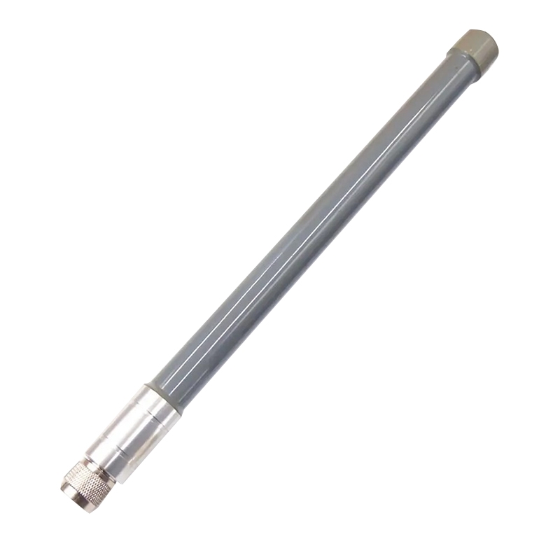
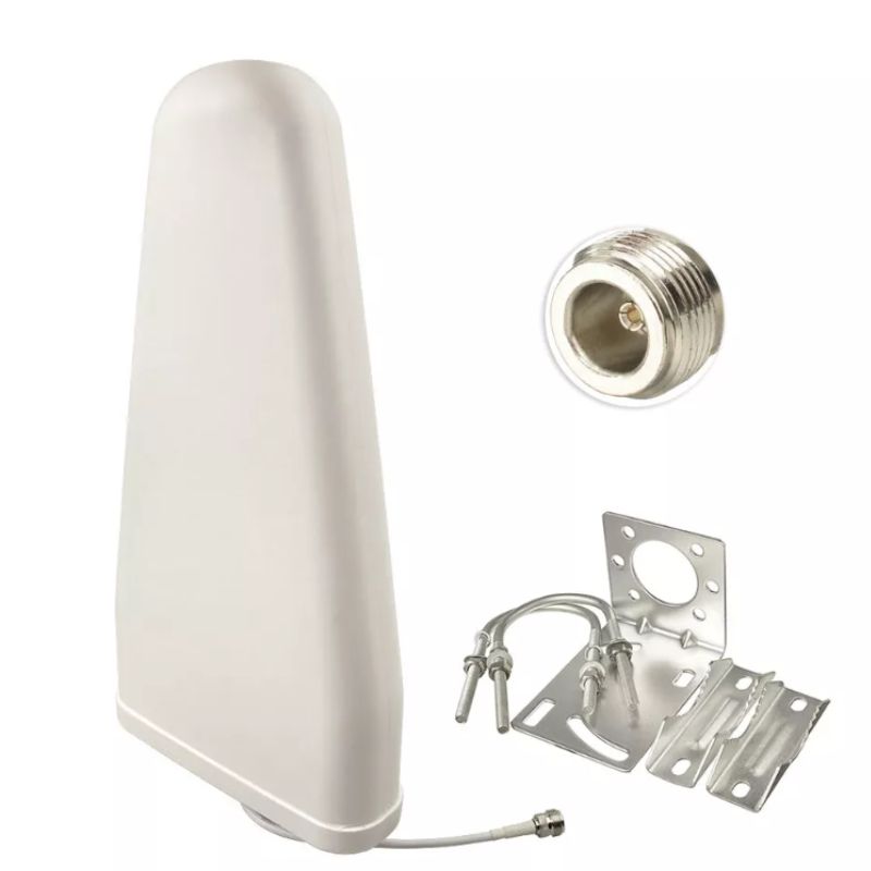
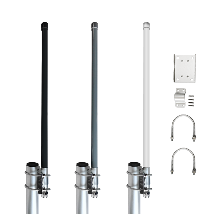
The VSWR (Voltage Standing Wave Ratio) is a measure of impedance matching between the antenna and the coaxial cable connecting it to the reader. A low VSWR (e.g., 1.5:1 or less at the center frequency) indicates efficient power transfer, minimizing reflected power that can damage the reader's transmitter. Finally, the IP Rating (Ingress Protection) defines the antenna's resilience to environmental factors. For harsh industrial or outdoor settings, antennas with a rating of IP67 (dust-tight and protected against immersion in water up to 1m) or IP68 (protected against long-term immersion) are essential to ensure long-term reliability and performance stability.
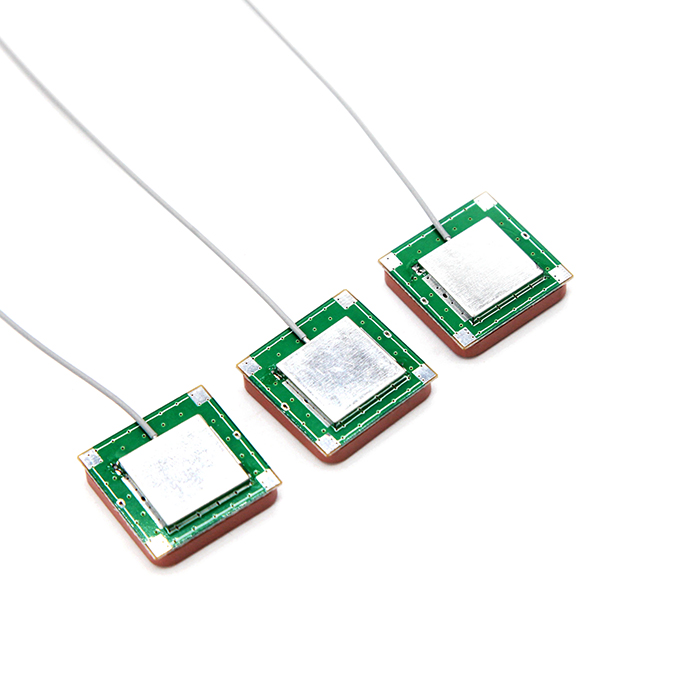
rfid antennas are deployed across a vast spectrum of industries due to their ability to identify and track objects without line-of-sight. In Supply Chain Management and Logistics, high-gain, circularly polarized UHF antennas are mounted on warehouse dock doors and portal frameworks to automatically read tags on pallets and cases as they pass through, enabling real-time inventory visibility and reducing manual scanning labor. In the Retail Sector, these systems are used for smart shelves (using near-field HF antennas) for item-level inventory tracking and for anti-theft electronic article surveillance (EAS), dramatically improving stock accuracy and reducing shrinkage.
The Healthcare industry utilizes RFID for asset tracking of mobile medical equipment like infusion pumps and wheelchairs, as well as for patient safety through wristband tracking. HF antennas are often preferred here for their shorter, more controlled read range, which prevents accidental reads of nearby items and ensures privacy. In Access Control and Security, LF (125 kHz) antennas are embedded in walls and turnstiles to read proximity cards, granting authorized personnel entry to secured facilities. Furthermore, Manufacturing and Industrial Automation rely on ruggedized, high-temperature-resistant antennas to track parts and tools along assembly lines, managing work-in-process and ensuring correct assembly sequences.
Emerging applications include Smart Agriculture, where UHF antennas track livestock, and Automotive systems for tire pressure monitoring and smart key entry. Each scenario demands a specific antenna type; a long-range, outdoor vehicle access gate requires a rugged, high-gain linear antenna, while a library's self-checkout kiosk uses a small, aesthetically pleasing HF antenna with a very localized field.
Proper maintenance is crucial for sustaining the optimal performance and longevity of an RFID antenna. Regular Physical Inspection is the first step. This involves checking the antenna housing for any signs of cracks, dents, or other physical damage that could compromise its IP rating and internal components. The antenna's mount and brackets should be inspected to ensure they remain secure and have not been loosened by vibration or environmental factors, which could misalign the radiation pattern and create read zones in unintended areas.
Cleaning the radome (the protective outer cover) is essential, especially in dirty environments like warehouses or manufacturing plants. Accumulated dust, grime, or oil on the radome can attenuate the RF signal, significantly reducing read range and reliability. The antenna should be cleaned periodically using a soft, lint-free cloth dampened with a mild, non-abrasive solvent or isopropyl alcohol. Harsh chemicals, abrasive materials, or high-pressure water jets must be avoided, as they can damage anti-reflective coatings or seals on the radome. For external antennas, checking for moisture ingress or corrosion on the connector and cable is vital.
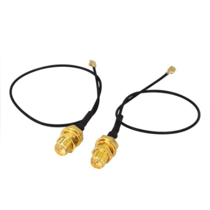
Connector and Cable Integrity are often the source of performance degradation. The coaxial connector at the back of the antenna and the cable itself should be inspected for wear, corrosion, or looseness. A poor connection will result in a high VSWR, causing significant signal loss and potentially reflecting power back to the reader, which can lead to internal damage over time. It is good practice to ensure connectors are hand-tightened and then secured a quarter-turn with a wrench, avoiding over-tightening. Cables should not be kinked or tightly bent, as this alters their impedance; the minimum bend radius (often 10x the cable diameter) must always be respected.
Finally, Performance Verification should be conducted periodically or after any physical maintenance. This can be done by benchmarking the system's read performance against a known baseline. Using a test tag placed at various points in the read field, one can check for a reduction in maximum read range or the appearance of dead zones. For a more precise analysis, a handheld spectrum analyzer or a dedicated RFID performance monitor can be used to measure the system's return loss or VSWR, confirming that the antenna and its connection are operating within the manufacturer's specified parameters.


Address: No.1 Sankeng Qinghutou Tangxia Dongguan Guangdong China TaiWan office: 558-2 ZhongHua,Zhubei,Xinzhu,Taiwan
Copyright © 2026 Dongguan RenFeng Electronic Technology Co.,Ltd All rights reserved.