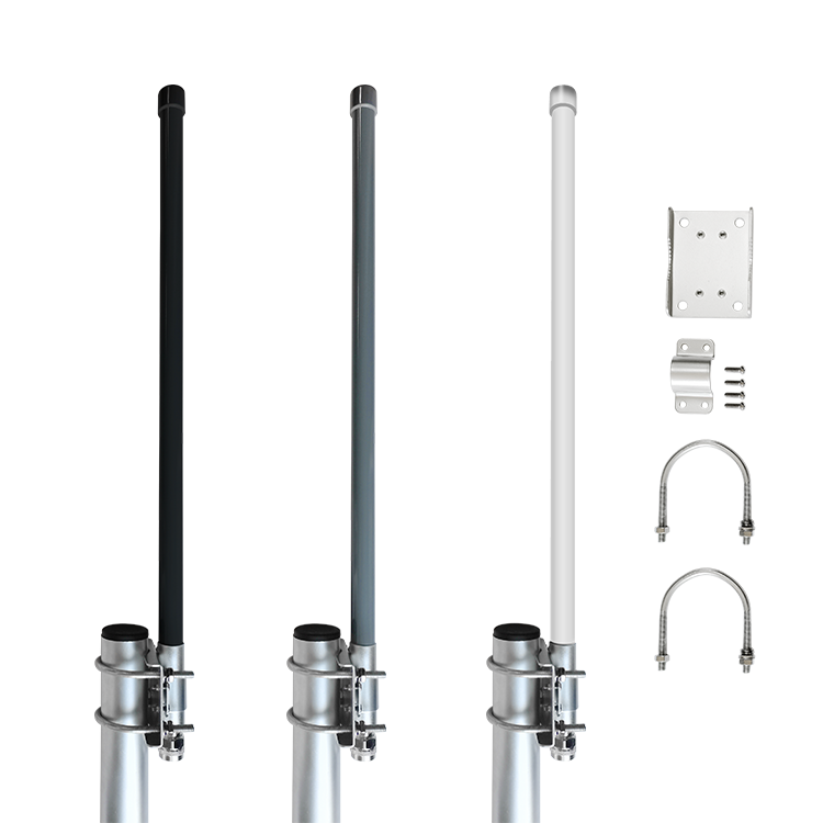
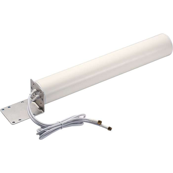
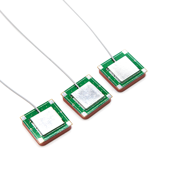
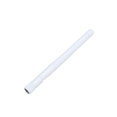
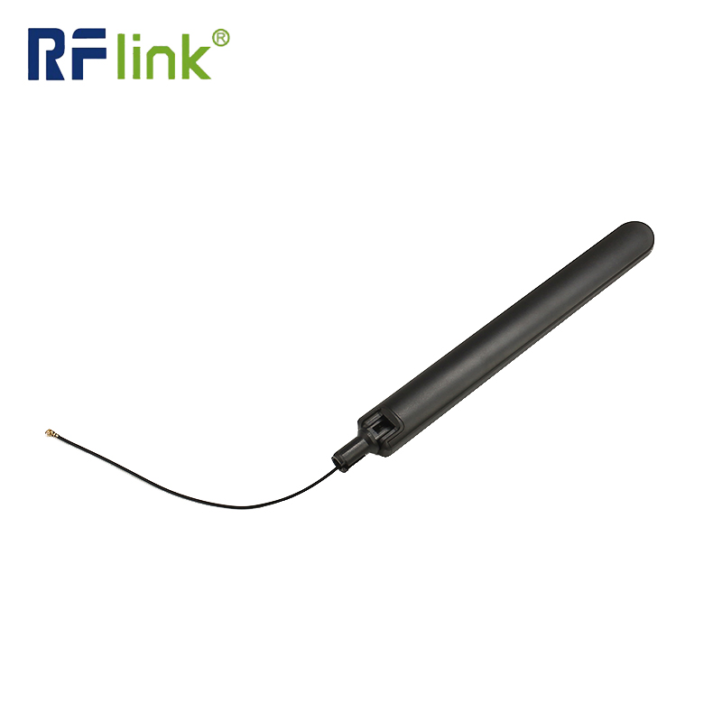
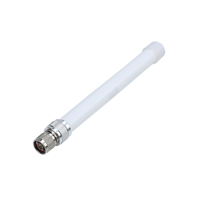
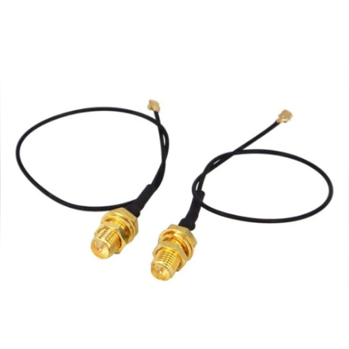
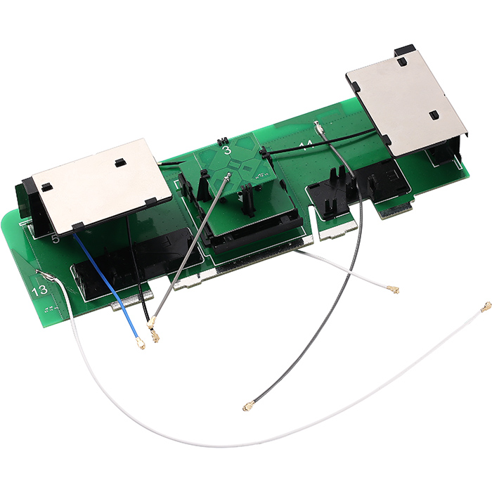
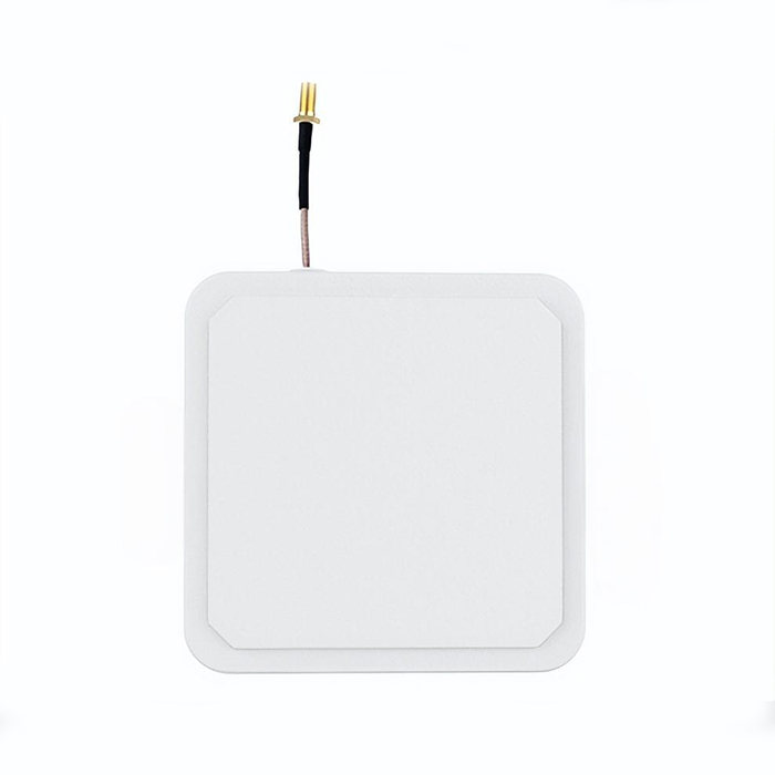
Radio Frequency (RF) connectors are specialized electronic components designed to maintain signal integrity while connecting coaxial cables in high-frequency applications. These precision-engineered interfaces ensure minimal signal loss and reflection across various frequency ranges, making them indispensable in modern telecommunications, aerospace, and electronic testing environments.
Key Characteristics with Technical Specifications
Impedance Matching
RF Connectors maintain precise impedance values to prevent signal reflections. The most common impedance standards include 50Ω (primarily for test equipment and wireless systems) and 75Ω (typically for video and cable television applications). High-quality connectors achieve Voltage Standing Wave Ratio (VSWR) values as low as 1.05:1 at 6 GHz, with some precision types maintaining 1.2:1 up to 18 GHz.
Frequency Range
Different connector types support specific frequency operational bands. Standard BNC connectors typically operate up to 4 GHz, while SMA variants can reach 18 GHz. Precision connectors like 2.92mm (K-type) support frequencies up to 40 GHz, and 1.85mm connectors can extend to 67 GHz. The upper frequency limit is primarily determined by the connector's physical dimensions and dielectric materials.
Power Handling Capacity
The maximum power transmission capability varies significantly among connector types. Standard SMA connectors typically handle 100-200 watts at 3 GHz, while N-type connectors can manage up to 500 watts average power at 1 GHz. High-power applications may require specialized connectors like 7/16 DIN, capable of handling 2,300 watts average power at 500 MHz.
Insertion Loss Performance
High-quality RF Connectors exhibit minimal insertion loss across their operational bandwidth. Typical values range from 0.05 dB to 0.2 dB per connector interface at lower frequencies, increasing to approximately 0.5 dB to 1.0 dB at millimeter-wave frequencies above 40 GHz. The loss characteristics are influenced by conductor material, dielectric properties, and surface finish quality.
Durability and Mechanical Specifications
rf connectors are rated for specific mating cycles while maintaining electrical performance. Commercial-grade connectors typically withstand 500 mating cycles, while military-specification versions can endure 1,000-5,000 cycles. Operating temperature ranges generally span from -65°C to +165°C, with specialized variants extending beyond these limits for extreme environment applications.
Environmental Sealing
Many RF connectors feature robust environmental protection. IP67-rated connectors provide complete dust ingress protection and can withstand immersion in water up to 1 meter depth for 30 minutes. Humidity resistance typically meets MIL-STD-202F standards, enduring 95% relative humidity at 40°C for extended periods without performance degradation.
Primary Application Scenarios
Telecommunications Infrastructure
RF connectors are fundamental components in cellular base stations, supporting 5G NR systems operating in sub-6 GHz and millimeter-wave bands up to 39 GHz. They facilitate connections between antennas, remote radio units, and baseband equipment while maintaining signal integrity across wide bandwidths exceeding 100 MHz per carrier.
Aerospace and Defense Systems
In radar systems, RF connectors interface between transceivers and antenna arrays, handling peak power levels exceeding 1 MW in some military applications. They maintain phase stability within ±2 degrees across temperature variations from -55°C to +85°C for phased array radar applications.
Test and Measurement Equipment
Precision RF connectors enable accurate signal analysis in vector network analyzers operating up to 1.1 THz. Calibration standards utilize connectors with repeatability better than 0.005 dB and 0.1 degrees for insertion loss and phase measurements respectively.
Satellite Communications
Space-grade RF connectors operate in vacuum conditions while withstanding vibration levels up to 20 G RMS and thermal cycling between -150°C to +125°C in low Earth orbit applications. They maintain stable performance throughout mission durations exceeding 15 years.
Medical Imaging Systems
In MRI systems, RF connectors interface between coils and processing units, operating at frequencies such as 127.8 MHz for 3T systems. They provide shielding effectiveness greater than 80 dB to prevent electromagnetic interference with sensitive medical measurements.
Comprehensive Maintenance Procedures
Regular Inspection Protocols
Perform visual examinations using magnification (10x-20x) to identify plating wear, contact deformation, or contaminant accumulation. Check for proper center conductor protrusion within 0.005-0.015 inches for SMA connectors and verify dielectric surfaces for cracks or carbon tracking.
Cleaning Procedures
Utilize solvent cleaning with isopropyl alcohol (99.9% purity) applied with lint-free swabs. For stubborn contaminants, use specialized RF connector cleaners that leave no residue. Avoid abrasive materials that could damage plating finishes with thicknesses typically between 50-200 microinches of gold over nickel.
Connection Handling
Always use calibrated torque wrenches specific to connector types: 7-10 in-lbs for SMA, 12-15 in-lbs for N-type, and 20-30 in-lbs for 7/16 DIN connectors. Avoid overtightening, which can cause thread damage and change impedance characteristics.
Storage Conditions
Store connectors in controlled environments with temperature maintained at 15-30°C and relative humidity below 60%. Use protective caps to prevent dust accumulation and mechanical damage. For long-term storage, employ vapor-corrosion inhibitor bags with oxygen scavengers.
Performance Verification
Conduct periodic VSWR measurements using calibrated test equipment. Replace connectors showing VSWR degradation beyond 1.5:1 from their specified values. Document insertion loss trends, investigating increases exceeding 0.2 dB above baseline measurements.
Preventive Maintenance Scheduling
Establish maintenance intervals based on operational cycles: inspect after 100 mating cycles for high-frequency applications (>18 GHz), 250 cycles for general use, and 500 cycles for infrastructure applications. More frequent inspections may be necessary in harsh environments with salt fog, dust, or extreme temperature exposure.


