


News
- Home
- Service
- Product Center
- Application
- About Us
- Videos
- News
- Contact Us

2025-10-31 10:01:01
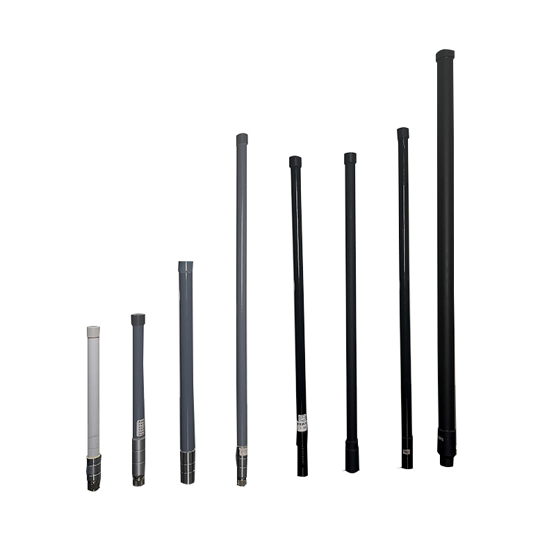
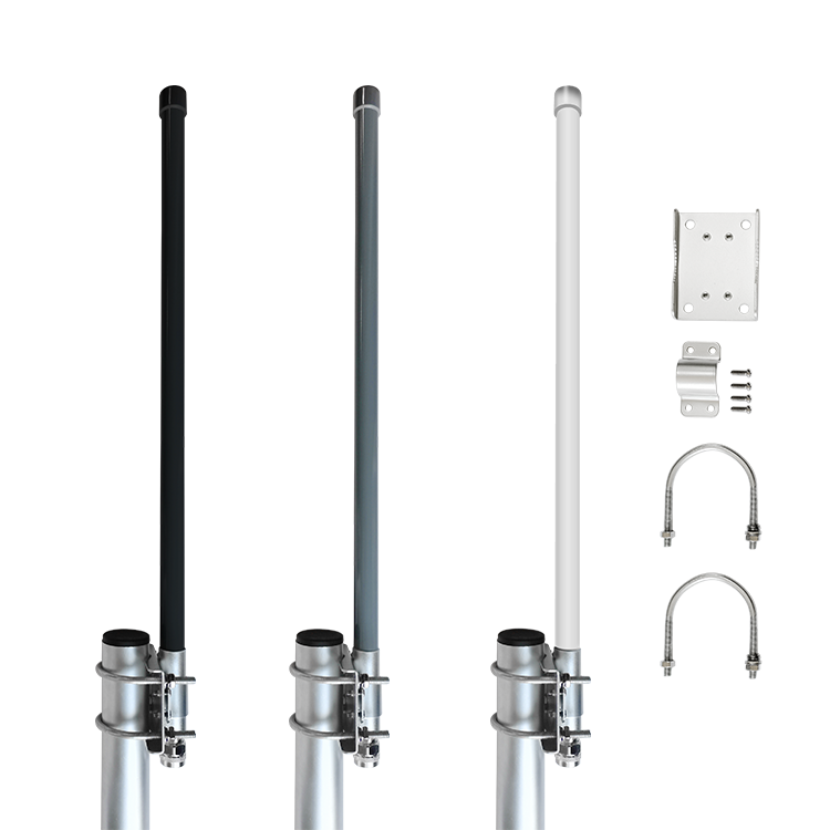
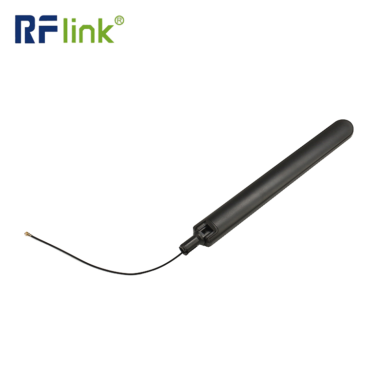
A waterproof outdoor fiberglass antenna represents a sophisticated telecommunications device engineered for reliable signal transmission and reception in challenging environmental conditions. These antennas combine advanced materials science with electromagnetic engineering principles to create robust, high-performance communication solutions.

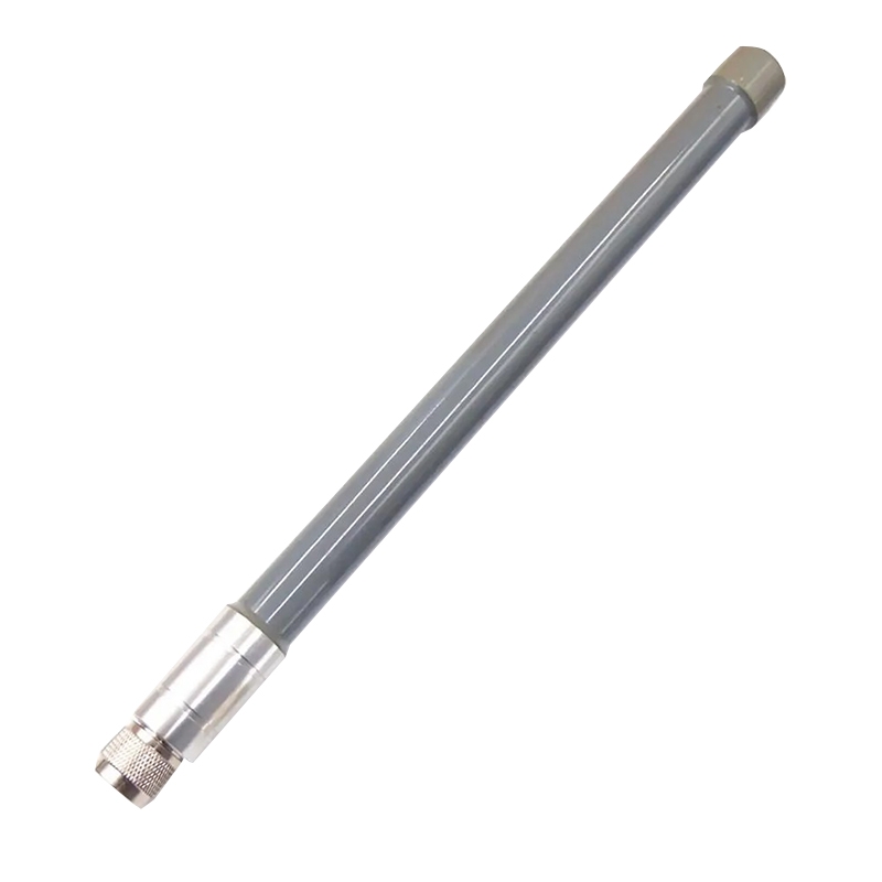
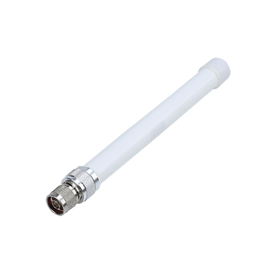
Weatherproof Construction: These antennas feature specialized sealing technologies including IP67 or higher ingress protection ratings, ensuring complete protection against dust ingress and water immersion up to 1 meter depth for 30 minutes. The fiberglass radome provides exceptional resistance to UV radiation, maintaining structural integrity through ≥10 years of continuous outdoor exposure.
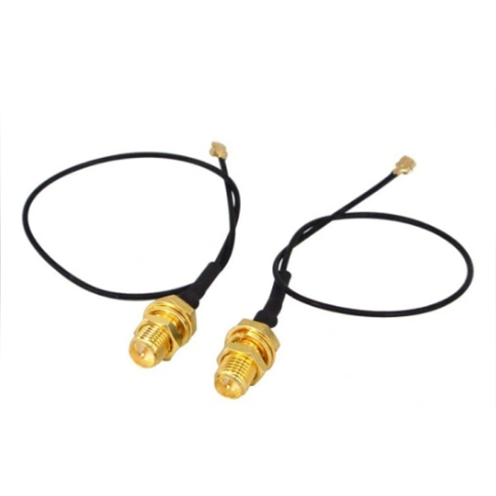
Electrical Performance: Modern Fiberglass Antennas demonstrate impressive electrical characteristics with VSWR ratios typically below 1.5:1 across their operational bandwidth. Gain specifications range from 3 dBi to 24 dBi, depending on the specific antenna design and frequency requirements. The impedance is standardized at 50 ohms with connector options including N-type, SMA, and TNC interfaces featuring ≥1000 mating cycles durability.
Mechanical Durability: The fiberglass composite construction enables these antennas to withstand wind loads up to 200 km/h without performance degradation. Operating temperature ranges typically span from -40°C to +85°C, with some specialized models capable of functioning in extreme conditions from -55°C to +125°C. The material composition provides excellent resistance to salt spray corrosion, making them suitable for coastal installations.
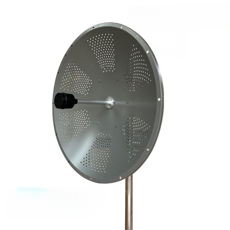
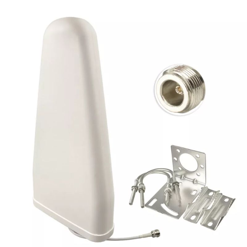
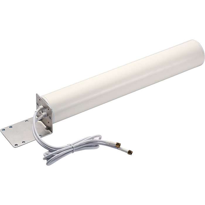
Radiation Pattern Efficiency: These antennas maintain consistent radiation patterns with front-to-back ratios exceeding 20 dB in directional models. The beamwidth can be precisely engineered from 360° omnidirectional coverage to highly focused 15° sector patterns for point-to-point applications. Polarization options include vertical, horizontal, and dual-polarization configurations with cross-polarization discrimination better than 30 dB.
Waterproof fiberglass antennas serve as critical components in cellular networks, supporting 4G LTE and 5G NR deployments. They provide coverage in macro cells with typical gain values of 17-21 dBi and facilitate small cell deployments with compact form factors. Their environmental resilience ensures 99.999% operational availability in diverse climatic conditions.
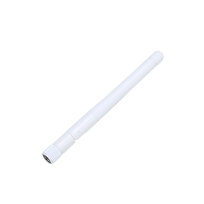
These antennas enable reliable communication for first responders operating in the 138-174 MHz VHF, 380-520 MHz UHF, and 700/800/900 MHz public safety bands. The mechanical stability ensures continued operation during natural disasters, with impact resistance capable of withstanding ICE loading up to 25 mm thickness.
In marine environments, these antennas provide critical communication links for vessel traffic systems, port operations, and offshore installations. Specialized models feature enhanced corrosion protection with salt spray testing exceeding 2000 hours per ASTM B117 standards. Marine-grade antennas typically operate in the 156-162 MHz VHF marine band with omnidirectional radiation patterns.
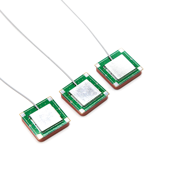
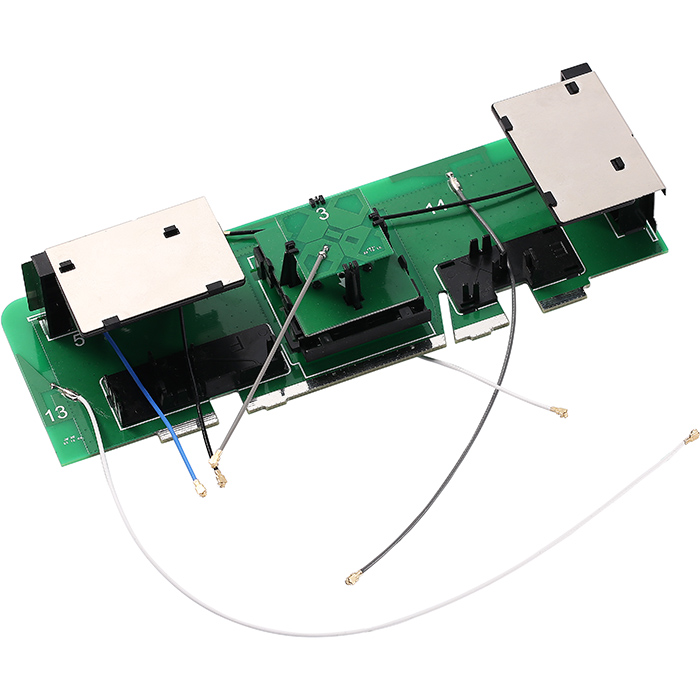
For industrial automation, these antennas connect remote sensors and control systems operating in license-free bands including 2.4 GHz and 5.8 GHz ISM bands, as well as 865-870 MHz and 902-928 MHz for regional applications. The antennas support data rates up to 300 Mbps with error vector magnitude (EVM) performance meeting modern modulation scheme requirements.
In broadcasting applications, fiberglass antennas transmit television and radio signals in the 88-108 MHz FM broadcast, 174-230 MHz VHF TV, and 470-862 MHz UHF TV bands. For WISPs, they provide point-to-point and point-to-multipoint connectivity with typical gains of 12-18 dBi for sector antennas and 23-28 dBi for parabolic grid designs.
Conduct visual inspections at 6-month intervals, examining the radome for hairline cracks, checking connector seals for integrity, and verifying mounting hardware security. Use optical magnification tools to detect micro-fractures that may compromise the IP rating. Document inspection results including photographs of any observed anomalies.
Inspect RF Connectors quarterly for corrosion or moisture ingress. Clean connectors using 99.9% isopropyl alcohol and lint-free wipes. Apply appropriate torque during reassembly: 15-20 Nm for N-type, 1.5-2.0 Nm for SMA. Use dielectric grease meeting MIL-G-81309 specifications for environmental sealing.
Annually verify the structural mounting using torque wrenches calibrated to ±4% accuracy. Check guy wires for proper tension (10-15% of breaking strength) and inspect for wear at contact points. For tower-mounted antennas, conduct structural analysis considering ice loading scenarios specific to the geographic region.
Implement continuous VSWR monitoring with threshold alarms set at VSWR > 2.0:1. Use calibrated spectrum analyzers with ±1.5 dB accuracy to measure received signal strength periodically. Maintain baseline performance records including radiation pattern measurements conducted in ANEchoic chambers during initial installation.
Reapply UV-protective coatings every 3-5 years using formulations with ≥98% UV radiation blockage. In coastal areas, perform more frequent inspections for salt deposition, cleaning with deionized water and pH-neutral detergents. Ensure drainage holes remain unobstructed to prevent water accumulation.
Test grounding systems semiannually using fall-of-potential method, maintaining earth resistance below 5 ohms. Inspect surge protection devices for indicator status and replace units that have exceeded their 8-10 year service life. Verify the integrity of ground bonding conductors using micro-ohmmeters with 0.1 mΩ resolution.
| Parameter | Typical Specification Range | Testing Standard |
|---|---|---|
| Frequency Range | 80 MHz6 GHz (model dependent) | ETSI EN 301 489 |
| VSWR | ≤1.5:1 (across operating band) | IEEE 149-2021 |
| Impedance | 50 Ω nominal | IEC 61169 series |
| Power Handling | 100-500 W average (dependent on design) | MIL-STD-188-164 |
| Lightning Protection | DC ground to chassis | IEC 62305 series |
| Material UV Resistance | ≥10 years outdoor durability | ASTM G154 Cycle 4 |
Example Installation Checklist
Clear line-of-sight verification
Structural load capacity assessment
Local regulation compliance check
VSWR measurement: ≤1.5:1
Continuity check: ∞ resistance (radome to ground)
Visual inspection: No visible defects
Use stainless steel hardware (304 or 316 grade)
Apply proper torque sequence
Install drip loops in cabling
Minimum 6 AWG copper grounding conductor
Multiple ground rod system (when required)
Exothermic welding for permanent connections
VSWR measurement at operating frequency
Radiation pattern verification (when possible)
Documentation completion
The advanced engineering and robust construction of waterproof outdoor fiberglass antennas make them indispensable components in modern wireless communication infrastructure. Their ability to maintain precise electrical characteristics while withstanding harsh environmental conditions ensures reliable performance across diverse applications. Proper maintenance following manufacturer recommendations and industry best practices extends service life and preserves optimal performance characteristics throughout the antenna's operational lifespan.


Address: No.1 Sankeng Qinghutou Tangxia Dongguan Guangdong China TaiWan office: 558-2 ZhongHua,Zhubei,Xinzhu,Taiwan
Copyright © 2026 Dongguan RenFeng Electronic Technology Co.,Ltd All rights reserved.