


News
- Home
- Service
- Product Center
- Application
- About Us
- Videos
- News
- Contact Us

2025-11-07 10:20:14
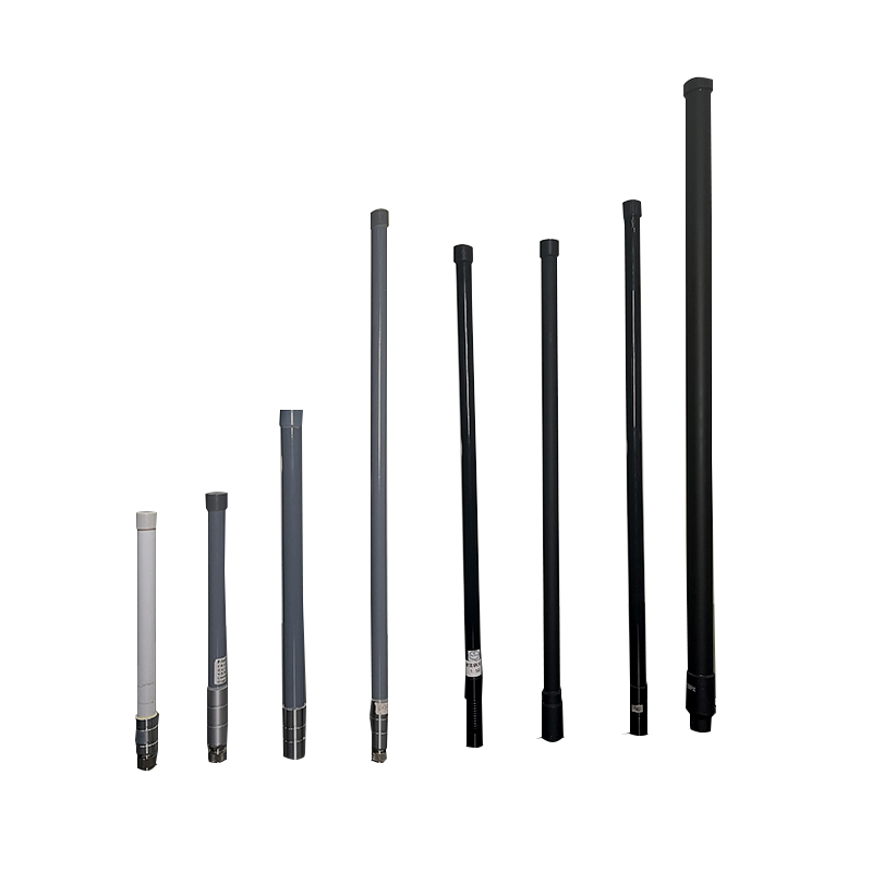
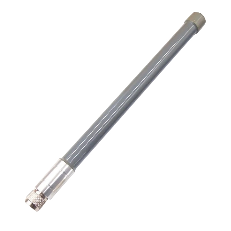
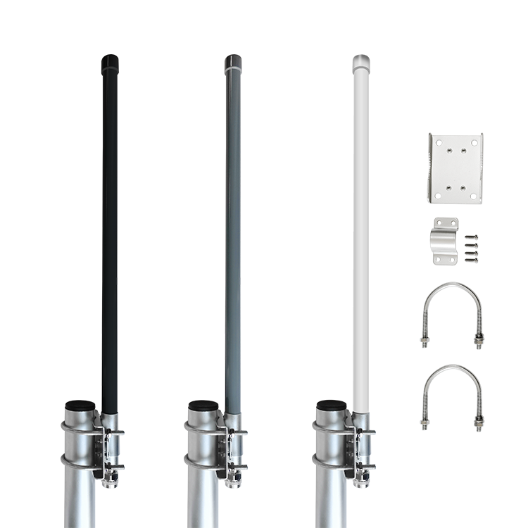
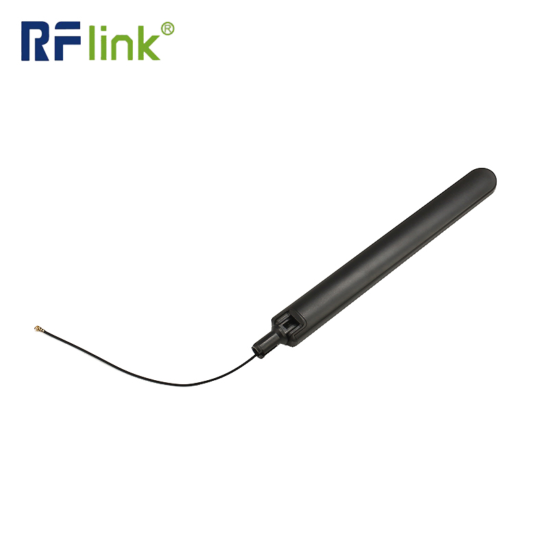
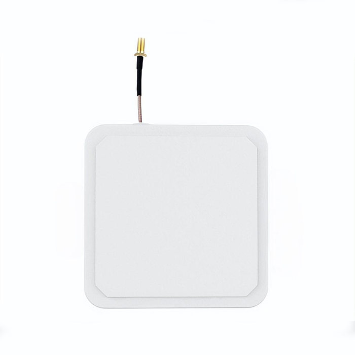
Epoxy fiberglass antennas represent a sophisticated class of radio frequency components that combine advanced composite materials with precision electromagnetic engineering. These antennas utilize a substrate composed of fiberglass cloth impregnated with epoxy resin, creating a dielectric material with exceptional electrical and mechanical properties. The manufacturing process involves carefully controlled lamination and curing stages to achieve optimal dielectric constant uniformity and dimensional stability. This construction method allows for the creation of antennas that maintain consistent performance across wide temperature ranges and harsh environmental conditions, making them particularly valuable for applications where reliability is paramount.
Epoxy Fiberglass Antennas exhibit several distinctive characteristics supported by precise technical data:
Dielectric Properties: The epoxy fiberglass substrate typically demonstrates a dielectric constant (εr) between 4.2 and 4.8 with a dissipation factor of 0.018 to 0.025 at 1 GHz. This controlled permittivity enables precise impedance matching and reduces signal loss, with typical return loss values better than -15 dB across the operational bandwidth.
Thermal Performance: These antennas maintain structural integrity across extreme temperatures, with an operating temperature range of -55°C to +150°C and a thermal coefficient of dielectric constant of +125 ppm/°C. The glass transition temperature (Tg) typically exceeds 130°C, ensuring dimensional stability under thermal stress.
Mechanical Durability: The composite structure provides exceptional mechanical strength with a tensile strength of 300-400 MPa and flexural strength of 400-500 MPa. The material exhibits water absorption rates below 0.1% after 24 hours immersion and demonstrates excellent resistance to chemicals, solvents, and UV radiation.
Electrical Performance: Epoxy fiberglass antennas typically achieve radiation efficiency of 85-92% in the frequency range of 500 MHz to 6 GHz, with voltage standing wave ratio (VSWR) values maintained below 1.5:1 across the designated bandwidth. The surface resistivity exceeds 10^12 Ω/square, minimizing surface leakage currents.
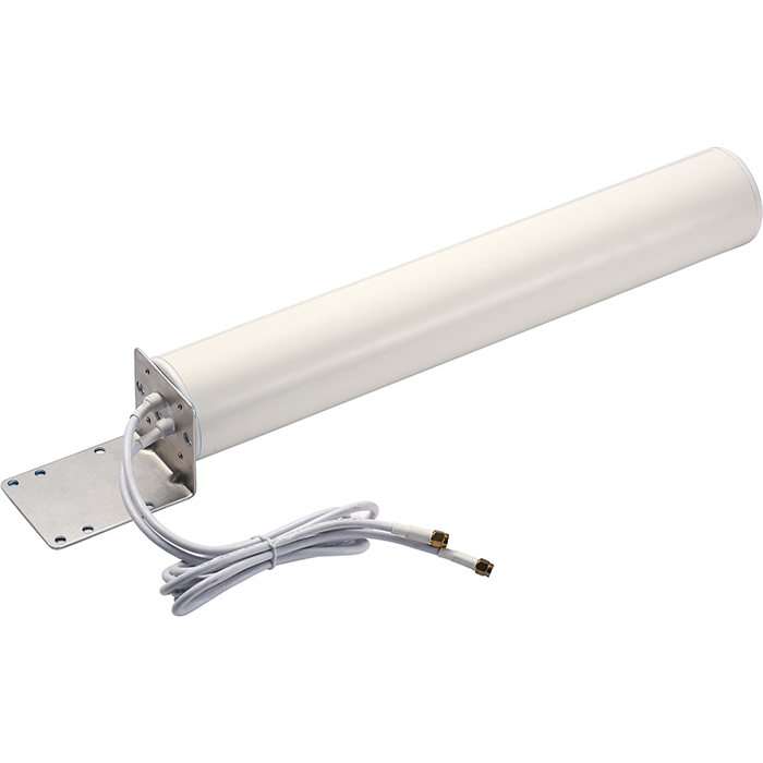
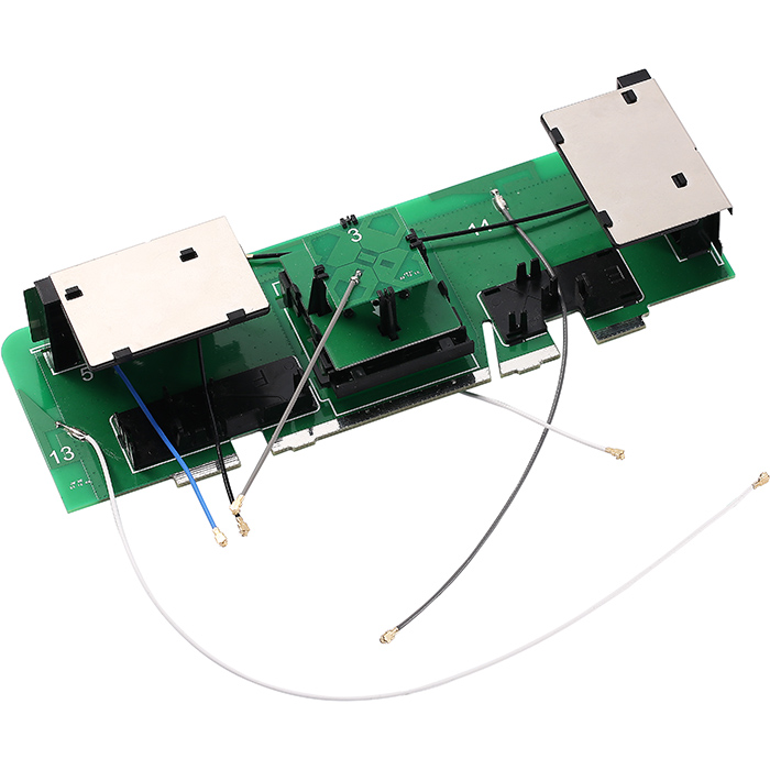
Epoxy fiberglass antennas are extensively deployed in cellular base stations, particularly for LTE (700-2700 MHz) and 5G (3.5-6 GHz) applications. Their environmental stability ensures consistent performance in outdoor installations, with typical gain values ranging from 6 dBi to 18 dBi depending on the specific application requirements.
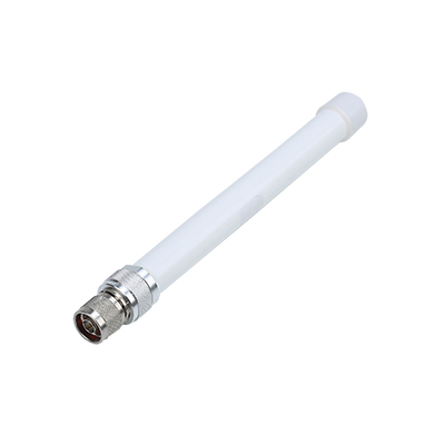
In marine environments, these antennas provide reliable communication for VHF (156-174 MHz) and UHF (400-470 MHz) maritime radio systems. The corrosion-resistant properties and ability to withstand salt spray exposure make them ideal for shipboard installations and coastal infrastructure.
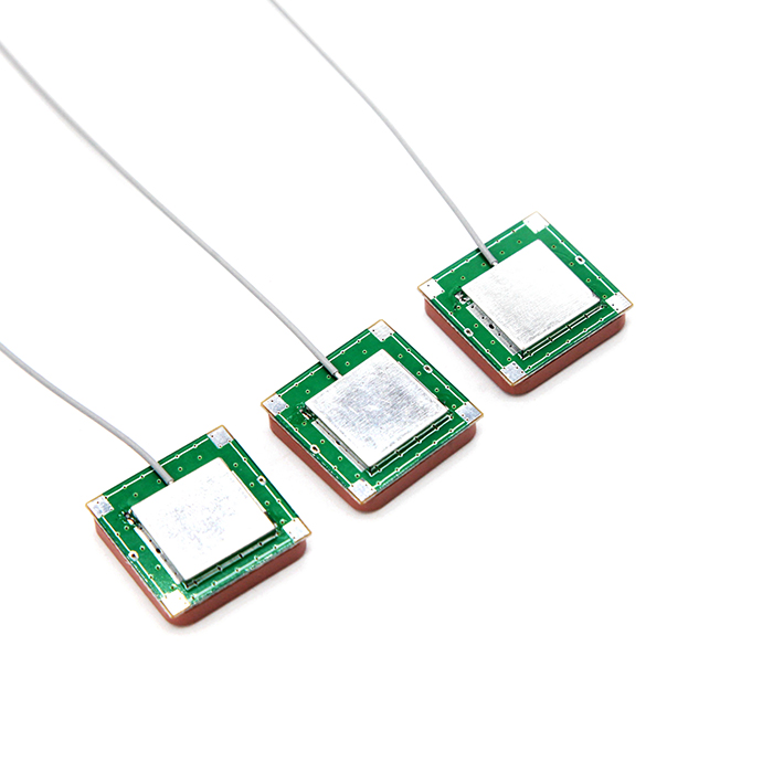
The aviation industry utilizes epoxy fiberglass antennas for ADS-B (1090 MHz), TCAS (1030/1090 MHz), and VOR (108-117.95 MHz) systems. Their lightweight construction (typical weight savings of 30-40% compared to metal equivalents) and resistance to aviation fuels and hydraulic fluids are critical advantages.
Emergency communication systems rely on these antennas for TETRA (380-400 MHz), P25 (136-174 MHz, 400-520 MHz), and first responder networks. The mechanical robustness ensures operation during natural disasters and emergency situations.
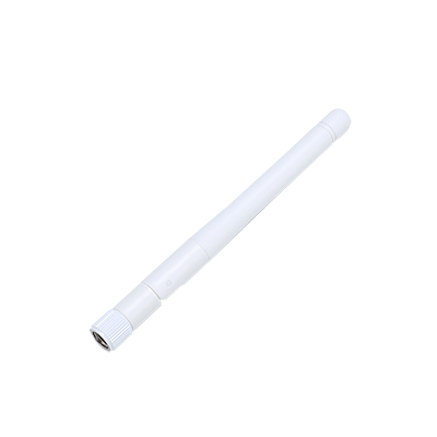
For industrial automation and smart city applications, epoxy fiberglass antennas support LoRaWAN (868/915 MHz), Sigfox (868 MHz), and NB-IoT bands. Their durability in industrial environments with exposure to chemicals, vibrations, and temperature fluctuations makes them suitable for factory automation and utility monitoring.
Conduct visual inspections quarterly, examining for cracks exceeding 0.5 mm in width, delamination, or discoloration. Use optical magnification to detect micro-fractures in the epoxy surface. Verify all mechanical connections for proper torque specifications, typically 10-15 Nm for mounting hardware depending on the antenna size.
Clean antenna surfaces every six months using isopropyl alcohol (70-99% concentration) and lint-free cloths. Avoid abrasive cleaners or solvents that may damage the epoxy surface. For salt deposit removal in coastal areas, use a distilled water rinse followed by isopropyl alcohol application.
Perform annual VSWR measurements using a calibrated vector network analyzer. Record baseline measurements when the antenna is installed and monitor for deviations exceeding ±0.2 in VSWR ratio or return loss degradation greater than 3 dB. Document radiation pattern changes using appropriate test equipment.
Inspect radomes and protective coatings for integrity. Reapply UV-protective coatings annually in high-sunlight environments. Check sealing compounds and gaskets for weatherproofing, replacing any components showing hardening or compression set exceeding 15% of original thickness.
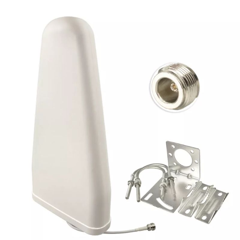
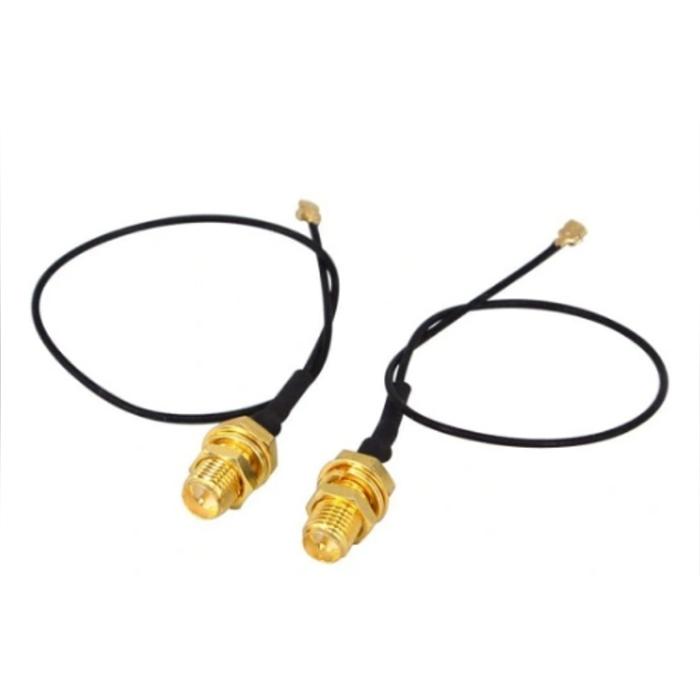
Inspect RF Connectors every six months for corrosion, proper engagement, and specified torque values (typically 2-4 Nm for N-type connectors). Verify cable integrity and support, ensuring bend radii exceed 10 times the cable diameter. Clean connector interfaces with appropriate contact cleaning solutions.
| Parameter | Typical Value | Test Condition | Standard |
|---|---|---|---|
| Dielectric Constant | 4.2 - 4.8 | 1 MHz, 23°C | IPC-TM-650 2.5.5.3 |
| Dissipation Factor | 0.018 - 0.025 | 1 MHz, 23°C | ASTM D150 |
| Volume Resistivity | 10^14 Ω·cm | 500 VDC, 23°C | IEC 60093 |
| Surface Resistivity | 10^12 Ω/square | 500 VDC, 23°C | IEC 60093 |
| Water Absorption | 0.08% | 24h immersion, 23°C | IPC-TM-650 2.6.2.1 |
| Flexural Strength | 450 MPa | 23°C | ASTM D790 |
| Thermal Coefficient of εr | +125 ppm/°C | -55°C to +125°C | IPC-TM-650 2.5.5.5 |


Address: No.1 Sankeng Qinghutou Tangxia Dongguan Guangdong China TaiWan office: 558-2 ZhongHua,Zhubei,Xinzhu,Taiwan
Copyright © 2026 Dongguan RenFeng Electronic Technology Co.,Ltd All rights reserved.