


News
- Home
- Service
- Product Center
- Application
- About Us
- Videos
- News
- Contact Us

2025-11-21 15:37:30
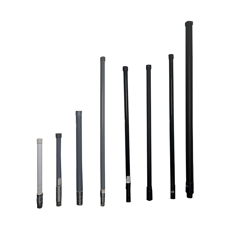
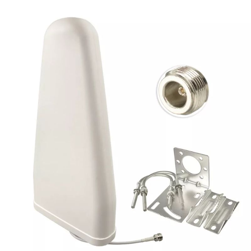
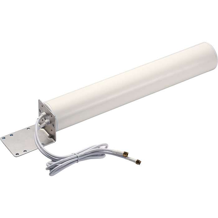
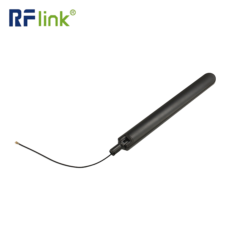
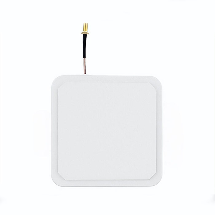
The radiation pattern of the 960 MHz wall - mount 4G LTE omni - directional MIMO antenna combines the characteristics of omni - Directional Antennas and MIMO technology. It presents a typical torus - like shape in 3D space, and has distinct and stable performance in both horizontal and vertical planes. Meanwhile, the multi - element design of MIMO further optimizes its radiation effect. Here is a detailed breakdown:

This antenna's overall radiation pattern is a standard torus (doughnut shape). The antenna itself is at the center of this torus. The reason for this shape is that the antenna radiates the most signal energy in the horizontal direction, while the energy gradually weakens as it deviates toward the vertical direction (directly above and below the antenna), and even drops to zero along the vertical axis of the antenna. This design is very practical. It avoids wasting signal energy on the sky or underground where there are generally no communication devices, and focuses the effective energy on the horizontal area where most terminal equipment is distributed. Unlike the theoretical spherical radiation of an isotropic antenna, this torus - shaped pattern is a result of balancing coverage and energy efficiency for actual communication needs.
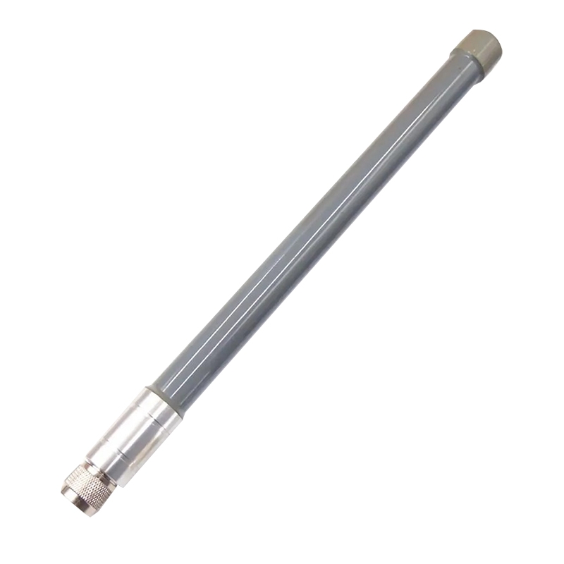
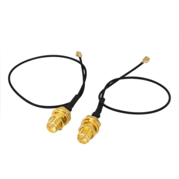
In the horizontal plane, it achieves true 360° uniform radiation. In the polar coordinate diagram of radiation intensity, its pattern is approximately a perfect circle. This means that terminal devices in any azimuth around the antenna within the same horizontal plane can receive signals of similar strength. For example, in a multi - room home or a small office with wall - mounted installation, devices in the living room, bedroom, and study can all obtain stable signals without the need for fine - tuning the antenna's horizontal orientation. However, in actual use, factors such as the antenna's feeder lines and the metal components of the mounting wall may have a slight impact on the horizontal radiation. To solve this problem, many models adopt a reasonable layout of radiating elements and shielding designs. For instance, some dipole - type MIMO antennas isolate the feeder lines to minimize interference and ensure the uniformity of horizontal radiation.
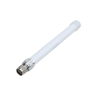
The vertical plane radiation is relatively narrow and shows a single broad lobe, and the specific beamwidth varies by model. Generally, the vertical half - power beamwidth (HPBW) of such antennas in the 960 MHz band is between tens of degrees. For example, the Cisco LTE - ANTM - D dipole antenna, which supports the 698 - 960 MHz band, has a vertical beamwidth that matches its low - gain characteristic (peak gain < 3.7 dBi) to meet indoor multi - floor or outdoor low - altitude terminal coverage. There is also a positive correlation between the vertical beamwidth and gain: the higher the antenna gain in the 960 MHz band, the narrower the vertical beamwidth. For example, some high - gain models with 5 dBi gain have a vertical beamwidth of only about 20 - 30°, which is suitable for long - distance horizontal signal transmission in open outdoor environments; while low - gain models with 3 dBi gain have a vertical beamwidth of up to 60 - 90°, which is more suitable for indoor scenarios where equipment is distributed at different heights, such as between desktops and shelves.
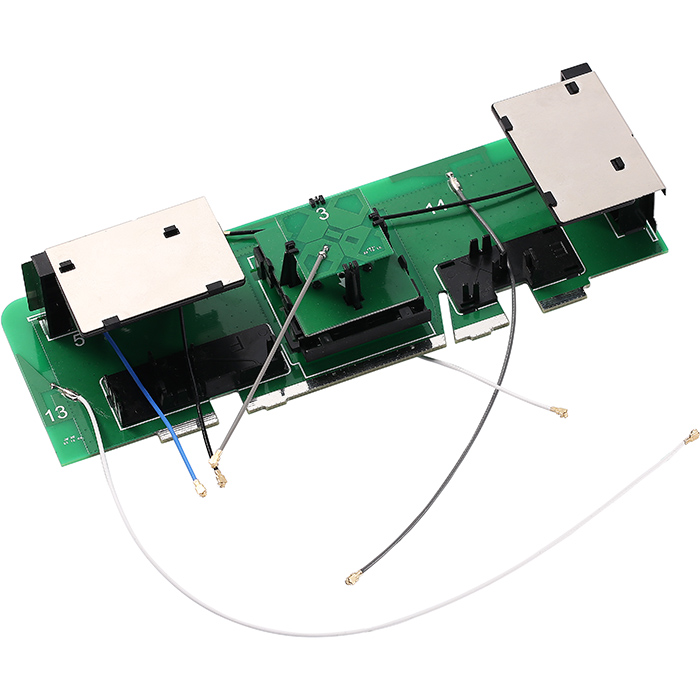
This antenna usually adopts a 2×2 MIMO structure, which is composed of two independent omni - directional radiating elements. These two elements do not interfere with each other while maintaining their respective torus - shaped radiation patterns. Their collaborative work brings two key optimizations. On one hand, it achieves spatial diversity. When one radiating element is affected by obstacles or signal fading, the other can receive and transmit signals through different paths, which ensures the stability of communication. On the other hand, the reasonable spacing between the two elements (usually matching the 960 MHz wavelength) avoids mutual coupling between signals while expanding the effective radiation coverage. In multipath propagation scenarios common in cities or buildings, this multi - element radiation design can significantly improve signal throughput and reduce bit error rates. For example, in an office with many walls and electronic equipment, the MIMO antenna can capture multiple reflected signal paths to make the connection of laptops, IoT sensors and other devices more stable.
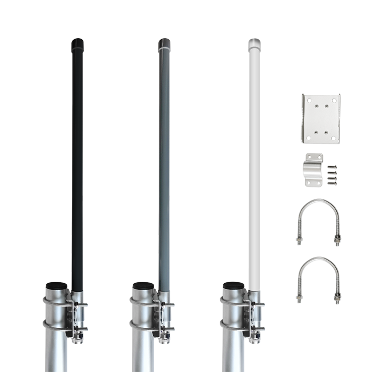
As a wall - mount antenna, its installation state will also have a subtle impact on the radiation pattern. Most models have adjustable joints that can be fixed at angles such as 0°, 45°, and 90°. When installed vertically, the vertical radiation is symmetric; when adjusted to a 45° angle, the main lobe of the vertical radiation will tilt slightly, which can adapt to scenarios where terminal equipment is concentrated on one side of the wall. In addition, installing it outdoors requires attention to the ground plane. For example, monopole - type radiating elements in MIMO antennas rely on the wall's metal - containing structure or an additional ground plane to stabilize the vertical radiation pattern. If installed on a non - metallic light wall, it may be necessary to add a metal backplane as required to avoid deformation of the vertical beam and ensure that the radiation pattern meets the design indicators.


Address: No.1 Sankeng Qinghutou Tangxia Dongguan Guangdong China TaiWan office: 558-2 ZhongHua,Zhubei,Xinzhu,Taiwan
Copyright © 2026 Dongguan RenFeng Electronic Technology Co.,Ltd All rights reserved.