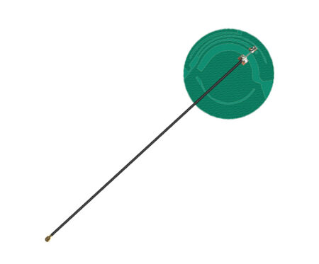
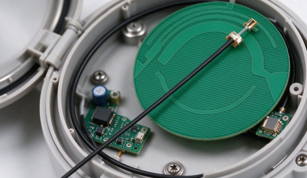
Renfeng’s 915MHz Round PCB Antenna is a compact internal RF component designed for wireless sensors and embedded IoT devices. It operates at 910–920MHz, provides 3dBi gain, and features an IPEX-1 connector with a 118mm RF1.13 cable. Its lightweight design weighs approximately 2g.
What Is a 915MHz Round PCB Antenna?
A 915MHz Round PCB Antenna is a compact printed circuit antenna designed to support wireless communication around the 915MHz frequency range. Its round structure makes it suitable for devices with circular housings or limited internal mounting space.
The term is defined as an embedded RF antenna that uses a printed conductive structure to transmit and receive radio frequency signals. Unlike larger external antennas, this type of component can fit inside compact electronic products without requiring a separate external mounting structure.
Renfeng’s 915MHz 3dBi Round PCB Embedded Antenna operates from 910–920MHz. It uses an IPEX-1 connector and a 118mm RF1.13 cable to connect with compatible wireless modules.
The main advantages include:
- Compact structure for space-limited device enclosures.
- 3dBi antenna gain for wireless communication applications.
- Lightweight construction at approximately 2g.
- IPEX-1 connection for embedded RF integration.
- Cable length customization for different device layouts.
How Does a Round PCB Embedded Antenna Work?
A Round PCB Embedded Antenna converts electrical signals into electromagnetic waves during transmission and converts received radio waves into electrical signals. Its conductive pattern and electrical characteristics determine how it performs within the specified frequency range.
Engineers design the antenna structure to achieve suitable impedance matching and radiation characteristics. They also consider the device ground plane, enclosure materials, and nearby electronic components. For example, metal housings, batteries, and circuit boards can influence antenna performance. Therefore, engineers should evaluate the antenna inside the complete device rather than relying only on its nominal gain or frequency specifications.
What Are the Key Specifications of This 915MHz PCB Embedded Antenna?
The Renfeng 915MHz PCB Embedded Antenna combines a narrow operating frequency range, 3dBi gain, and a lightweight structure for compact wireless products.
| Parameter | Specification |
|---|---|
| Product Name | 915MHz 3dBi Round PCB Embedded Antenna |
| Operating Frequency | 910–920MHz |
| Antenna Gain | 3dBi |
| Connector | IPEX-1 |
| Cable | 118mm RF1.13 |
| Product Weight | Approximately 2g |
| Installation | Internal device mounting |
| Customization | Cable length and device-level integration |
The 910–920MHz operating range makes this antenna relevant to compatible sub-GHz wireless applications. However, developers should confirm that the frequency range matches the regional radio regulations and the wireless module’s operating requirements.
The 3dBi gain rating provides one performance reference. Engineers should also evaluate radiation patterns, antenna efficiency, polarization, and installation conditions to understand actual device performance.
Which IoT Devices Can Use a LoRaWAN PCB Antenna?
A LoRaWAN PCB Antenna can support compatible wireless sensor products when its frequency range matches the communication module and regional network requirements.
Typical applications include:
- Wireless sensors: Environmental monitoring, temperature measurement, and remote data collection.
- Smart meters: Compact metering equipment with internal wireless communication.
- Circular instruments: Round meters and electronic instruments with limited internal mounting space.
- LoRaWAN terminals: Embedded devices operating on compatible sub-GHz frequency allocations.
- Industrial IoT products: Monitoring terminals and wireless control equipment.
A 915MHz IoT Sensor Antenna may suit devices designed for compatible regional frequency plans. However, LoRaWAN frequency configurations vary between regions, so engineers should verify the exact supported channels before selecting an antenna.
How Should Engineers Choose a Compact Internal Antenna?
Engineers should choose a Compact Internal Antenna by checking frequency compatibility, installation space, connector type, cable routing, and measured RF performance.
The following factors help guide antenna selection:
- Frequency compatibility: Confirm that the 910–920MHz range matches the wireless module and target application.
- Physical dimensions: Check the available mounting area inside the device enclosure.
- Connector compatibility: Verify that the IPEX-1 connector matches the module-side RF interface.
- Cable routing: Evaluate whether the 118mm RF1.13 cable reaches the connection point without installation constraints.
- Weight requirements: Consider the approximately 2g antenna weight when designing compact or lightweight products.
- Installation environment: Assess nearby metal components, batteries, and circuit boards.
Engineers should also test the antenna after installation because the enclosure and surrounding components can change its RF characteristics.
How Does a 915MHz Round PCB Antenna Compare with Other Antenna Types?
A 915MHz Round PCB Antenna provides a compact internal mounting option, while other antenna structures may offer different installation flexibility and RF characteristics.
| Antenna Type | Main Characteristics | Key Consideration |
|---|---|---|
| Round PCB Antenna | Compact printed structure | Requires suitable internal placement |
| FPC Embedded Antenna | Flexible substrate and adaptable positioning | Needs appropriate mounting space |
| External Whip Antenna | External mounting and flexible positioning | Requires enclosure access |
| Rigid PCB Antenna | Fixed structure integrated with a circuit board | Depends on PCB layout and ground plane |
Compared with traditional external antenna solutions, a Compact Internal Antenna can reduce the need for external mounting space and support a more integrated product structure.
However, external antennas may provide greater positioning flexibility when the internal enclosure limits radiation performance. The appropriate option depends on the device design, available space, and RF test results.
What Affects the Cost of a Custom 915MHz PCB Antenna?
The cost of a custom 915MHz PCB antenna depends on its RF design requirements, physical structure, connector, cable configuration, and production quantity.
The main cost factors include:
- Antenna structure: Different PCB layouts and physical dimensions may require specific design work.
- RF requirements: Frequency coverage and performance targets influence design and tuning requirements.
- Connector selection: IPEX-1 and other connection options may have different component costs.
- Cable customization: Cable type and customized length affect material and assembly costs.
- Device integration: Special enclosure structures may require additional engineering evaluation.
- Production quantity: Prototype development and batch production involve different preparation and manufacturing requirements.
Providing the target frequency, device dimensions, connector specifications, and expected production quantity helps suppliers evaluate the project more accurately.
How Should Engineers Test a 915MHz PCB Embedded Antenna?
Engineers should verify a 915MHz PCB Embedded Antenna through RF measurements and device-level testing under the intended installation conditions.
Common evaluation methods include:
- S11 and return loss testing: Use a vector network analyzer to evaluate impedance matching across 910–920MHz.
- VSWR testing: Measure voltage standing wave ratio to assess impedance matching.
- Radiation pattern testing: Use an anechoic chamber to evaluate antenna radiation characteristics.
- Efficiency testing: Measure antenna radiation efficiency under defined test conditions.
- Device-level testing: Evaluate wireless communication performance after installing the antenna inside the final enclosure.
The exact test plan should follow the product specification and target application. Certification requirements depend on the final device and destination market. Engineers should confirm applicable regulatory standards and certification status through project documentation rather than assuming that antenna specifications guarantee regulatory compliance.
FAQ: What Should Buyers Know About 915MHz Round PCB Antennas?
What Is a 915MHz Round PCB Antenna Used For?
A 915MHz Round PCB Antenna provides internal wireless connectivity for compact electronic products. Typical applications include compatible LoRaWAN terminals, wireless sensors, smart meters, and circular instruments.
How to Choose a 915MHz PCB Embedded Antenna for IoT Sensors?
Check the operating frequency, antenna gain, physical installation space, connector, and cable length. Engineers should also verify regional frequency requirements and test the antenna inside the complete device.
Why Does Antenna Placement Affect IoT Sensor Performance?
Antenna placement affects impedance matching, radiation patterns, and signal efficiency. Nearby batteries, metal housings, and circuit boards can influence RF performance, so engineers should evaluate the antenna in its final installation environment.
Source & Expertise
This article references the product specifications of Renfeng’s 915MHz 3dBi Round PCB Embedded Antenna. Renfeng focuses on smart communication terminal antennas and customized antenna solutions. Its product scope includes PCB antennas, FPC antennas, embedded antennas, and other RF components for wireless communication applications.
The company has experience in antenna research and development, with RF engineers averaging more than 10 years of industry experience. Its technical capabilities cover antenna structure recommendations, RF design support, cable customization, and production delivery.
Renfeng supports antenna integration according to different device structures and communication requirements. Its services cover the development process from concept evaluation and design to manufacturing and batch delivery. Certification and compliance requirements depend on the final product and destination market. Buyers should request relevant test reports and certification documents when evaluating a specific antenna or complete wireless device. No unverified certification or test result is claimed in this article.
Last Updated: November 2, 2026