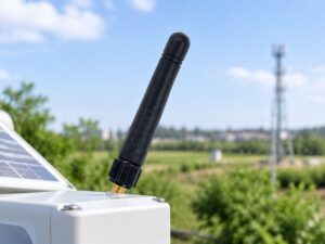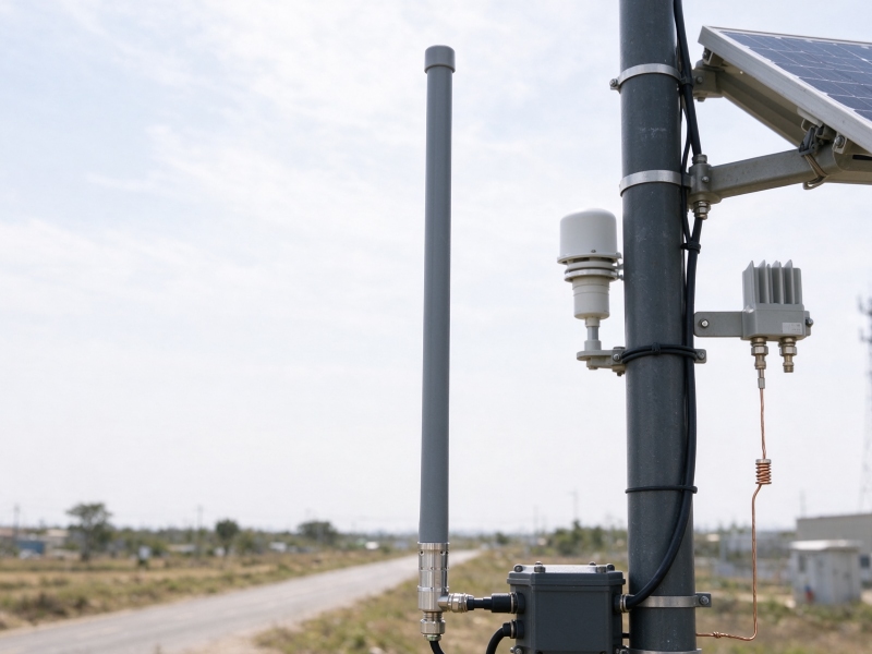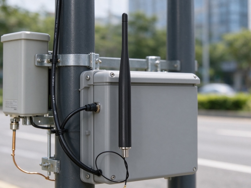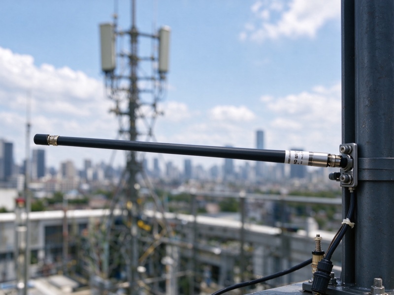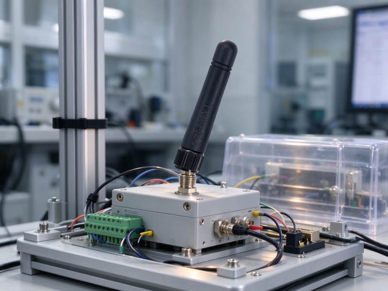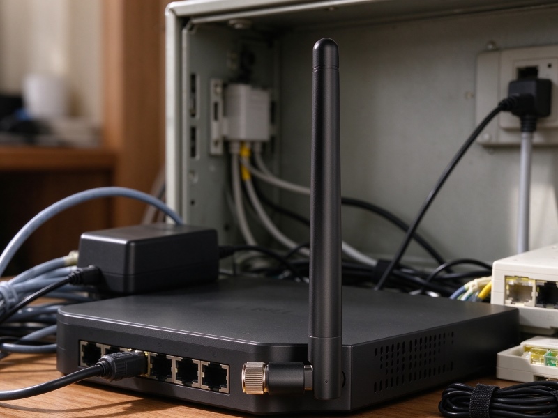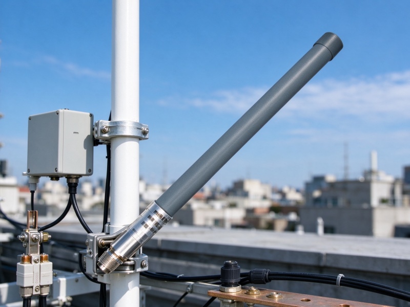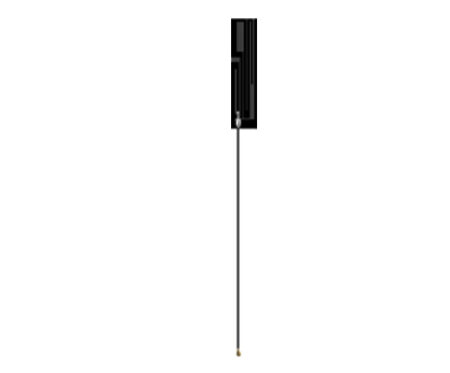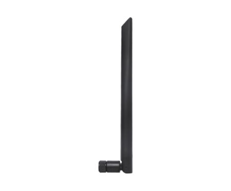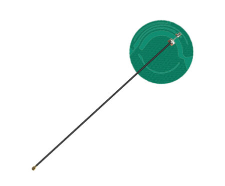
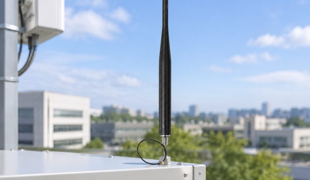
Renfeng’s 868MHz Cabinet Whip Antenna is an external RF antenna designed to connect LoRa gateways and compact wireless devices. It covers 832–920MHz, provides 3dBi gain, and uses an IPEX-1 connector with a 150mm feedline. Its 165mm antenna body supports flexible integration into cabinets and other equipment enclosures.
What Is an 868MHz Cabinet Whip Antenna?
An 868MHz Cabinet Whip Antenna is an external antenna designed to support sub-GHz wireless communication in LoRa gateways, IoT equipment, and enclosed electronic devices. It uses a whip-style radiating element and a cable connection to link the antenna to an internal RF port.
The product is defined as a 3dBi whip antenna with an operating frequency range of 832–920MHz. Its main physical and electrical specifications include:
| Parameter | Specification |
|---|---|
| Product type | Cabinet whip antenna |
| Frequency range | 832–920MHz |
| Nominal frequency | 868MHz |
| Gain | 3dBi |
| Connector | IPEX-1 |
| Feedline length | 150mm |
| Antenna body length | 165mm |
These specifications help engineers assess frequency coverage, cable routing, and available installation space. However, the frequency range alone does not confirm compatibility with every regional LoRa or LoRaWAN channel plan. The radio configuration and local frequency regulations must also match.
How Does a Whip Antenna Connect to a LoRa Gateway?
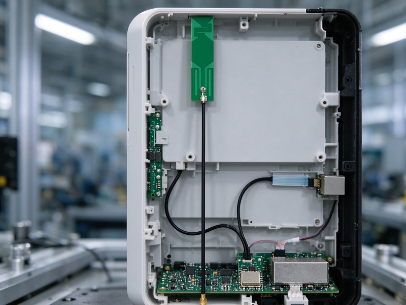
A whip antenna connects to a LoRa gateway through an RF cable and a compatible connector, allowing the antenna to operate outside or away from the main circuit board. In this design, the IPEX-1 connector links the 150mm feedline to the device’s corresponding RF interface.
The basic signal path follows three steps:
- The gateway’s RF circuit generates or receives a radio-frequency signal.
- The IPEX-1 connection and feedline transfer the signal between the circuit and antenna.
- The antenna radiates or receives electromagnetic energy through its radiating element.
The 150mm cable gives hardware designers some flexibility when positioning the antenna relative to the circuit board or enclosure. Nevertheless, cable routing, connector compatibility, nearby metal components, and enclosure materials can affect RF performance. Engineers should also confirm that the device uses the correct IPEX connector version and mating interface.
How Do the Frequency, Gain, and Dimensions Affect Integration?
The frequency range, gain, and physical dimensions determine whether an antenna fits the device’s radio design and mechanical structure. For this model, the 832–920MHz range covers the nominal 868MHz operating frequency, while the 3dBi gain provides a reference for antenna performance.
The 165mm antenna body is an important mechanical consideration. Designers should check the available clearance around the cabinet, the antenna’s mounting position, and the distance from nearby conductive parts. A suitable installation should avoid unnecessary obstruction and maintain the intended antenna orientation.
The main advantages include:
- Flexible cable positioning: The 150mm feedline allows the antenna to connect to an internal RF port without placing the antenna directly on the circuit board.
- External installation: The whip structure can be positioned outside a device enclosure when the mechanical design provides a suitable mounting arrangement.
- Sub-GHz coverage: The 832–920MHz frequency range supports designs operating within the antenna’s specified band.
- Defined gain: The 3dBi rating gives engineers a reference point for comparing antenna options.
Gain alone does not determine communication distance. Transmitter power, receiver sensitivity, antenna placement, cable loss, interference, and the surrounding environment also influence the actual link performance.
Where Can This Cabinet Whip Antenna Be Used?
This antenna can be considered for LoRa gateways, IoT equipment, smart cabinets, and industrial control devices that require an external sub-GHz antenna connection. Its cable-based structure is relevant when the RF circuit and antenna need separate mounting positions.
Typical application scenarios include:
- LoRa gateways: Connecting an external antenna to gateway hardware designed for a compatible frequency band.
- Smart cabinets: Supporting wireless communication in monitoring or control equipment housed inside cabinets.
- Industrial IoT devices: Providing an antenna option for sensor gateways and communication terminals.
- Wireless monitoring equipment: Supporting sub-GHz links in remote monitoring and data collection devices.
Compared with traditional PCB-mounted solutions, an external whip antenna can provide more freedom in antenna placement. However, the final result depends on the enclosure, mounting method, ground reference, and RF layout. It should not be assumed to deliver better coverage in every installation.
How Should Engineers Choose an Antenna for a LoRa Gateway?
Engineers should select an antenna by checking radio frequency compatibility, connector type, cable length, mechanical clearance, and measured RF performance. A product that matches the nominal frequency may still be unsuitable if its connector or installation arrangement does not fit the device.
Before selecting an antenna, review these points:
- Frequency compatibility: Confirm that the antenna’s operating range covers the gateway’s configured channels and regional requirements.
- Connector matching: Check that the device uses an IPEX-1 interface compatible with the antenna cable.
- Cable routing: Confirm that 150mm provides enough length without creating excessive bends or unnecessary cable loops.
- Mechanical clearance: Allow sufficient space for the 165mm antenna body and its mounting position.
- RF validation: Test antenna performance in the final enclosure rather than relying only on standalone specifications.
An omnidirectional antenna is often considered when a device needs coverage in multiple horizontal directions. However, the actual radiation pattern of this model should be confirmed through a measured antenna pattern rather than assumed from its whip appearance.
How Does a Cabinet Whip Antenna Compare With Other Antenna Types?
A cabinet whip antenna differs from PCB, FPC, and larger external antennas mainly in its structure, installation method, and space requirements.
| Antenna type | Installation | Main consideration |
|---|---|---|
| Cabinet whip antenna | External or enclosure-mounted | Requires body clearance and a suitable RF connection |
| PCB antenna | Directly on the circuit board | Depends strongly on PCB layout and ground design |
| FPC antenna | Inside the enclosure | Offers flexible placement but needs suitable adhesive space |
| Larger external antenna | Outside the equipment | May require more mounting space and a different cable arrangement |
The appropriate choice depends on the device’s mechanical design and RF requirements. A cabinet whip design is worth evaluating when the equipment supports an external antenna position and needs a cable connection to its internal RF circuit.
What Factors Affect Cabinet Whip Antenna Costs?
Antenna costs depend on the frequency design, gain target, connector, cable specification, materials, production volume, and customization requirements. Changes to cable length, connector type, antenna dimensions, or mechanical structure may affect manufacturing complexity.
For OEM and ODM projects, engineers should define the RF and mechanical requirements before requesting a quotation. This helps manufacturers assess whether the existing design meets the application or requires further development.
What Should Engineers Test Before Deployment?
Engineers should validate antenna performance in the complete device because the enclosure and installation environment can change RF characteristics. Recommended checks include:
- Impedance and matching: Measure VSWR or return loss across the intended operating band.
- Radiation pattern: Check horizontal and vertical radiation behavior in the final mounting configuration.
- Efficiency and gain: Verify performance using an appropriate antenna measurement setup.
- Cable and connector integrity: Inspect the IPEX-1 connection, cable routing, and mechanical retention.
- System communication: Evaluate packet delivery, RSSI, and SNR under representative operating conditions.
For products intended for European short-range radio applications, engineers should review the applicable regional regulatory requirements, including relevant ETSI EN 300 220 provisions where they apply. This reference does not mean that this antenna has been certified or tested to that standard. Regulatory compliance must be assessed for the complete radio equipment and its intended market.
FAQ: What Do Engineers Often Ask About Cabinet Whip Antennas?
What is an 868MHz antenna used for?
An 868MHz antenna supports wireless communication in compatible sub-GHz systems, including certain LoRa and IoT applications. The exact permitted channels depend on the region and device configuration.
How to choose a cabinet whip antenna for a LoRa gateway?
Check the operating frequency range, gain, connector interface, feedline length, antenna dimensions, and measured RF performance. Also confirm that the antenna fits the gateway enclosure and regional radio configuration.
Why does antenna placement affect LoRa gateway connectivity?
Antenna placement affects signal propagation because nearby metal, enclosure materials, cable routing, and mounting orientation can influence antenna performance. Testing the antenna in the final device helps identify installation-related losses.
How Does Renfeng Support Antenna Development?
Renfeng is a manufacturer focused on intelligent communication terminal antennas and customized antenna solutions. Established in 2012, the company supports antenna development for wireless communication equipment and IoT-related applications.
Its RF engineers have an average of more than 10 years of industry experience. The team can provide design and customization support based on device structure, RF requirements, connector selection, and cable configuration. These capabilities are relevant to equipment developers evaluating antenna integration for gateways, smart cabinets, and industrial communication terminals. No specific product certification or compliance report was provided for this antenna. Buyers should request the relevant test reports and regulatory documentation when a project requires them.
Source & Expertise
This article is based on the supplied product specifications for the 868 MHz 3 dBi Cabinet Whip Antenna with IPEX Connector and the company information provided by Renfeng. Technical explanations describe general antenna integration principles. Actual RF performance should be confirmed through testing in the target device and installation environment.
Last Updated
October 30, 2026